Solve PCB antenna disconnection problem
PCB antennas are becoming increasingly popular in the world of wireless communications due to their compact size, easy integration, and low manufacturing cost. However, one of the common issues faced by users of PCB antennas is the problem of disconnection or signal dropouts. In this article, we will examine the reasons behind this problem and suggest some effective solutions.
Reasons for PCB Antenna Disconnect
The primary reason for PCB antenna disconnect is poor antenna design or improper manufacturing techniques. If the antenna is not designed to match the specific frequency of the circuit or if the manufacturing techniques are not optimized, then the antenna may not be capable of achieving a consistent connection. Another reason for this problem is the interference of the designed system, which can introduce noise and affect the signal quality. Factors such as the location of the antenna on the PCB board, trace layout, and ground plane all contribute to the stability and reliability of the antenna connection.
Solutions for PCB Antenna Disconnect
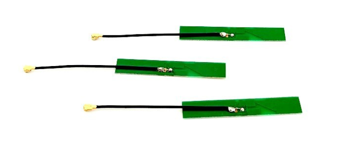
1. Optimize Antenna Design
Correct antenna design is critical for ensuring the antenna's stability and reliability. Keep in mind the manufacturing process, soldering techniques, and the PCB traces' layout when designing the antenna. The other factor to consider is the ground plane, which is essential in ensuring signal quality. The ground plane acts as a reference plane for the antenna, and any mismatch or interference can weaken the signal and result in signal dropouts. Work with an experienced PCB designer who knows how to optimize antenna design for maximum signal strength.
2. Test the Antenna
Test the antenna before integrating it into the final product, especially if it is a custom design. Make sure that the frequency matches the circuit's operational frequency and double-check the impedance match. Use impedance analyzers or spectrum analyzers to ensure that the antenna's return loss is low and close to the operating frequency. This step can prevent performance issues in the later stages because of poor antenna design.
3. Optimize the Trace Routing
Trace routing is another essential factor to consider when designing a PCB antenna. The routing of the traces determines the quality of the signal and the impedance match. A significant area to focus on when routing traces on the PCB is to minimize the losses between the transmission line and antenna. If the trace is too long or has excessive bends, it can cause reflection, which is a particular type of interference that results in signal dropouts. The best practice is to shorten the trace as much as possible, avoid sharp bends, and minimize the number of vias.
4. Avoid Interference
Interference from the circuit components can lead to a weak connection or signal dropout. Have a noise reduction strategy to avoid interference from other components, like a power supply. Separate the power supply and ground plane with a ferrite bead or capacitor to prevent noise from entering the circuit. Another solution is to place the antenna on the opposite side of any noise sources.
5. Perform Regular Maintenance
Regular maintenance is essential to ensure the reliability of the antenna connection. Check for loose connections, damaged traces, or any other anomalies that may cause signal disruption. Inspect any environmental factors that may be affecting the antenna, like changes in temperature, humidity levels or moisture, as they can cause connectivity issues.
A good PCB antenna design and proper manufacturing techniques can help mitigate the issue of signal dropouts or antenna disconnects. Some tips to keep in mind include optimizing the antenna design, testing it, optimizing trace routing, avoiding interference, and performing regular maintenance. By following these tips, you can ensure that your PCB antenna can maintain a stable and reliable connection, improving the overall functionality of the device.
